YouTube channel > Otomon YouTube Channel
Facebook Channel: Otomon Vintage FB
Why Negative Feedback Is the Audiophile’s Enemy
We could, in most cases, apply active techniques to make the specifications look even more impressive — but if doing so strips away originality or musical character, we will not do it. Our aim is to build equipment that sounds beautiful, not equipment that measures beautifully.
At OTOMON, music is judged by the ear and no instrument can replicate the human 's ear.
You can read
Japanese version here > https://otomon.net/articles/negative-feedback-ja.html
Vietnamese version here > https://otomon.net/articles/negative-feedback-vi.html
Why Negative Feedback Is the Audiophile’s Enemy
A mathematical analysis of how negative feedback affects the harmonic spectrum of audio signals
Abstract. Negative feedback (NFB) is a fundamental technique for reducing distortion and noise and for stabilising the gain of an amplifier. Yet many listeners feel that amplifiers with heavy feedback sound dry, lack dynamics and seem unnatural. This article analyses mathematically the mechanism by which negative feedback acts on the signal: the depth of feedback falls with frequency, so the higher-order harmonics of distortion are suppressed far less than the lower-order ones.
Readers who are not interested in mathematics may skip the derivations and go straight to the Remarks, Section 5 and Section 6.
1. Introduction
It is often said that negative feedback makes an amplifier sound slow, dry, unnatural and lacking in dynamics. These, however, are subjective impressions of listeners. This article seeks a quantitative explanation: how does negative feedback act on an audio signal, and which of its effects can rob the sound of its natural character?
The article is organised as follows:
- Benefits of negative feedback.
- Mathematical model of a negative feedback system.
- How negative feedback affects the sound.
- Conclusions and practical application.
2. Benefits of Negative Feedback
The greatest benefit of negative feedback is that it corrects errors
in the amplifier’s output signal, making specifications such as hum,
background noise and total harmonic distortion (THD) look better. With a
loop gain  (defined in
Section 3), negative feedback provides three effects established since
the work of H. S. Black (1934):
(defined in
Section 3), negative feedback provides three effects established since
the work of H. S. Black (1934):
- Distortion and noise generated inside the feedback loop are reduced
by the factor
 :
:  .
. - Output impedance is reduced by the same factor:
 , giving
better control of the loudspeaker (a higher damping factor).
, giving
better control of the loudspeaker (a higher damping factor). - The closed-loop gain becomes less sensitive to component variations:
when
 ,
,  .
.
However, negative feedback is a double-edged sword when engineers overuse it to polish an amplifier’s specifications. Amplifier design is not merely a matter of measurements at the output. It is a whole process of harmonising the gain stages and minimising hum, noise and harmonic distortion every time the signal passes through a component such as a resistor, a capacitor or a transformer. Negative feedback should not be used to correct design flaws; it should only be the ribbon tied on a gift before it is handed to its owner.
3. Mathematical Model of a Negative Feedback System
3.1. Basic quantities
In a negative feedback system (Black, 1934; Bode, 1945), the quantity that determines the amount of feedback is the loop gain:

where  is the open-loop gain
of the amplifier and
is the open-loop gain
of the amplifier and  is
the transfer ratio of the feedback network. The amount of feedback
actually applied to the signal is determined by
is
the transfer ratio of the feedback network. The amount of feedback
actually applied to the signal is determined by  , not by
  or
or  alone.
The feedback factor is defined as:

It is the denominator of the closed-loop transfer function:

The magnitude  is
called the depth of feedback at frequency
is
called the depth of feedback at frequency  and is usually expressed in dB as
 .
.
3.2. Frequency dependence of
 and
and 
Every physical amplifier has a frequency response. The general model is:

where  is the DC gain,
 are the zeros and
  are the poles. Hence
  always varies with
  .
.
The feedback network  is
frequency-dependent as well. Even when designed to be purely resistive,
in practice:
is
frequency-dependent as well. Even when designed to be purely resistive,
in practice:

owing to stray capacitance, wiring inductance and the frequency response of the components in the feedback network. In a tube amplifier whose feedback loop encloses the output transformer, the transformer’s frequency response is the most important source of poles.
Since both  and
and  depend on frequency, the
loop gain
depend on frequency, the
loop gain  , and therefore
the depth of feedback
, and therefore
the depth of feedback  ,
are frequency-dependent.
,
are frequency-dependent.
3.3. Single-pole amplifier model
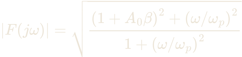
Consider an amplifier with a single pole and a purely resistive feedback network:

Loop gain and feedback factor:

Depth of feedback at frequency  :
:
Numerical example. Take  (DC loop gain of 9, so
that the depth of feedback at DC is
(DC loop gain of 9, so
that the depth of feedback at DC is  , i.e. 20 dB) and a pole frequency
  kHz (
kHz ( rad/s):
| Frequency |  |
 |
Depth of feedback |
|---|---|---|---|
| 20 Hz | 0.002 | 10.0 | 20.0 dB |
| 1 kHz | 0.1 | 9.95 | 20.0 dB |
| 10 kHz | 1 | 7.11 | 17.0 dB |
| 60 kHz | 6 | 1.92 | 5.7 dB |
| 100 kHz | 10 | 1.41 | 3.0 dB |
 ,
,  kHz)
kHz)Remark. The depth of feedback falls from 20 dB at 20 Hz to only about 3 dB at 100 kHz. In other words, high-frequency components receive far less feedback than low-frequency components.
3.4. Proof of monotonicity by differentiation
For the single-pole model, the squared depth of feedback is:

Let 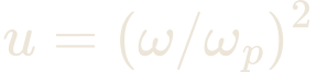 and
and  , so
that
, so
that 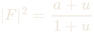 . Differentiating with respect to
  :
:

Since  , this
derivative is always negative. Moreover
, this
derivative is always negative. Moreover  increases with
  , with
 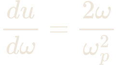 . By the chain rule:
![\frac{d|F|^{2}}{d\omega} = -\,\frac{\left[\left(A_{0}\beta\right)^{2} + 2A_{0}\beta\right]\cdot 2\omega/\omega_{p}^{2}}{\left(1 + \omega^{2}/\omega_{p}^{2}\right)^{2}} < 0 \quad \text{for all } \omega > 0](/nfb-formulas-dark/eq-054.png)
Conclusion. For the single-pole model, the depth of
feedback  decreases monotonically as frequency rises. The rate of
decrease is not constant but depends on
decreases monotonically as frequency rises. The rate of
decrease is not constant but depends on  : very slow when
  , fastest around
 and above.
3.5. General case: multi-pole amplifier
For an amplifier with  poles:

- At low frequencies (
 ):
):  , the deepest feedback.
 - At very high frequencies (
 ):
):  , feedback practically vanishes.
 - Where
 ,
,  . Each pole makes
  fall by a further 20 dB/decade, so
the depth of feedback falls at the same rate.
fall by a further 20 dB/decade, so
the depth of feedback falls at the same rate.
4. How Negative Feedback Affects the Sound
Every sound, whether a voice or a musical instrument, consists of a fundamental and a series of harmonics. It is this harmonic structure that gives a singer’s voice and an instrument’s timbre their character. Two kinds of harmonics passing through an amplifier must be clearly distinguished:
- Harmonics of the original signal: part of the sound to be reproduced.
- Harmonics generated by the amplifier itself (distortion): foreign components that are not in the recording.
Negative feedback acts on these two kinds of harmonics through two different mechanisms.
4.1. Effect on the harmonics of the original signal
The original signal contains many harmonics:
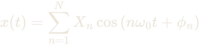
Considering only the linear part of the amplifier, this signal passes
through the closed-loop transfer function  :
:

Note that the amplitude of the  -th harmonic is multiplied by
  , not by
  . For the single-pole model of
Section 3.3:
. For the single-pole model of
Section 3.3:
![H(j\omega) = \frac{A_{0}}{1 + A_{0}\beta + j\omega/\omega_{p}} = \frac{A_{0}/\left(1 + A_{0}\beta\right)}{1 + j\omega/\left[\omega_{p}\left(1 + A_{0}\beta\right)\right]}](/nfb-formulas-dark/eq-074.png)
Feedback moves the pole of the system from  kHz up to
  kHz. Comparing the 20th harmonic (20 kHz) with the 1 kHz
fundamental:
kHz. Comparing the 20th harmonic (20 kHz) with the 1 kHz
fundamental:
| Without feedback | With feedback ( ) ) |
|
|---|---|---|
| Amplitude of 20 kHz relative to 1 kHz | −6.95 dB | −0.17 dB |
| Phase shift at 20 kHz | −63.4° | −11.3° |
Remark. In linear terms, negative feedback does not distort the harmonic structure of the original signal; on the contrary, it flattens the amplitude and phase response. The cause of the loss of naturalness must therefore be sought in the non-linear part, i.e. in the distortion generated by the amplifier, analysed in Section 4.2.
4.2. Effect on distortion generated by the amplifier
Distortion generated inside the feedback loop at frequency  is suppressed by the factor
  . If the fundamental has
frequency
. If the fundamental has
frequency  , the
, the  -th harmonic distortion lies at
  and is suppressed by the
factor:
and is suppressed by the
factor:

With  kHz,
kHz,  kHz,
kHz,  :
:
Harmonic  |
Frequency |  |
Suppression factor  |
Suppression |
|---|---|---|---|---|
| 1 | 1 kHz | 9.95 | 0.101 | −20.0 dB |
| 2 | 2 kHz | 9.81 | 0.102 | −19.8 dB |
| 3 | 3 kHz | 9.58 | 0.104 | −19.6 dB |
| 5 | 5 kHz | 8.96 | 0.112 | −19.0 dB |
| 10 | 10 kHz | 7.11 | 0.141 | −17.0 dB |
| 20 | 20 kHz | 4.56 | 0.219 | −13.2 dB |
Remark. Second-harmonic distortion is suppressed by almost 20 dB, whereas 20th-harmonic distortion is suppressed by only about 13 dB, a difference of about 7 dB. The residual distortion spectrum after feedback is therefore shifted towards the higher-order harmonics. THD may be very low, but the remaining distortion is concentrated in the higher-order harmonics, which many authors consider more objectionable to the ear than the lower-order ones.
Influence of feedback depth. This difference depends
directly on the depth of feedback. Table 4 shows by how many dB the 2nd
harmonic is suppressed more than the 6th, the 20th and the 50th
harmonics, for various depths of feedback (same  kHz,
kHz,  kHz). Without feedback the
difference is zero, meaning the amplifier’s harmonic structure is
preserved.
kHz). Without feedback the
difference is zero, meaning the amplifier’s harmonic structure is
preserved.
| Depth of feedback (DC) | 2nd vs 6th harmonic | 2nd vs 20th harmonic | 2nd vs 50th harmonic |
|---|---|---|---|
| 3 dB | 0.5 dB | 2.1 dB | 2.8 dB |
| 5 dB | 0.8 dB | 3.3 dB | 4.5 dB |
| 10 dB | 1.0 dB | 5.4 dB | 8.6 dB |
| 20 dB | 1.2 dB | 6.7 dB | 13.0 dB |
| 40 dB | 1.2 dB | 6.8 dB | 14.0 dB |
Remark. With light feedback (3–5 dB), the ratios between harmonics change by only about 2–4.5 dB. With heavy feedback (20–40 dB), they change by as much as 7–14 dB: THD falls sharply, but the amplifier’s inherent harmonic structure is substantially altered. Between the 2nd and 6th harmonics, both of which lie well below the pole at 10 kHz, the change is small (0.5–1.2 dB); it grows rapidly for harmonics near and above the pole frequency.
5. Mathematical Conclusions
In a practical negative feedback system, the distortion suppression
factor at frequency  is:
is:
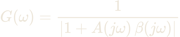
This quantity is a function of  and, in the single-pole model,
decreases monotonically with frequency. The ratio of the distortion
suppression at the
and, in the single-pole model,
decreases monotonically with frequency. The ratio of the distortion
suppression at the  -th harmonic to
that at the fundamental is:
-th harmonic to
that at the fundamental is:

When  , this ratio is
approximately
, this ratio is
approximately  for all
  : the higher the harmonic order,
the less the distortion is suppressed.
: the higher the harmonic order,
the less the distortion is suppressed.
From the above analysis we conclude:
- Harmonics of the original signal pass through the closed-loop system without additional linear distortion; feedback even flattens the frequency and phase response.
- Distortion generated by the amplifier is suppressed unevenly: low-order harmonics are strongly suppressed, high-order harmonics weakly. The residual distortion spectrum shifts towards the higher-order harmonics.
- The deeper the feedback, the greater the alteration of the harmonic structure: from about 2–4.5 dB at 3–5 dB of feedback up to 7–14 dB at 20–40 dB (Table 4).
- The extent of these effects depends on the depth of feedback
 , the pole positions
  , the fundamental frequency
 of the signal and the
non-linear characteristics of each gain stage.
of the signal and the
non-linear characteristics of each gain stage.
Thus negative feedback can make THD figures look excellent while at the same time changing the character of the distortion: the ratios between harmonics are altered, the residual distortion shifts to higher orders, and the deeper the feedback, the greater the change. This offers a plausible basis for the common observation that amplifiers with heavy feedback sound dry and less natural, despite better measurements.
6. Practical Application
If you use negative feedback to correct design flaws, you will need very deep feedback. THD can then be extremely low, but as shown in Sections 4 and 5, the residual distortion shifts to the higher-order harmonics and the amplifier’s inherent harmonic structure is substantially altered.
This does not mean that negative feedback is pure poison. It is like an antibiotic: used correctly, in the right dose and in the right place, it is an excellent weapon. When negative feedback is used to improve output specifications, around 10 dB or more is usually needed to make a clear difference to THD.
Therefore, to obtain beautiful sound before any feedback is applied, the first step is to use good components and to reduce non-linear distortion as far as possible. In a tube amplifier in particular, the heart and most important component is always the interstage transformer.
Next, the design must be uncompromising. An amplifier almost never has just one gain stage. In a tube amplifier, the gain of each stage is low, so one or two gain stages are usually needed before the power stage. Each gain stage produces its own harmonic distortion and hum. If the design is not good enough, the distortion of the stages accumulates and the total distortion at the output stage soars. Conversely, if the design is good enough, the harmonic distortion of the stages can cancel each other; the better the design, the greater the cancellation, and the amplifier’s specifications will be excellent even without feedback.
In the OUDDC circuit design, the distinctive coupling between the gain stages meets exactly this criterion. That is why, in almost all our amplifiers, since the specifications are already good enough without it, we keep the use of feedback to an absolute minimum in order to preserve the original character of the sound.
Most OTOMON amplifiers use no feedback at all. In certain special cases, a very small amount of negative feedback (typically 3–5 dB) is applied to lower the output impedance and help control the bass, the range most prone to losing control. According to Table 4, at this level the harmonic structure changes by only about 2–4.5 dB, far less than the 7–14 dB of deep feedback. Some amplifiers also offer a switch to select feedback on or off, so that listeners can experience for themselves the difference between with and without feedback, and how the sound changes as the amount of feedback changes.
References
- H. S. Black, “Stabilized Feedback Amplifiers”, Bell System Technical Journal, vol. 13, 1934.
- H. W. Bode, Network Analysis and Feedback Amplifier Design, Van Nostrand, 1945.